Opening: When time becomes a "controllable variable"
Have you ever thought that there is a "time magician" hidden behind the precise start and stop of the production line, the orderly operation of the motor, and the intelligent flashing of the lights? The ten-function time relay uses 10 delay modes to weave an industrial control time network so that every electrical action can be performed according to the "script". Today, we will dismantle this "time steward" in the field of automation and see how it uses time logic to leverage efficient control!
10 Delay Ranges: Make The Most Of Your Time
Power-On Delay: add a "Buffer Zone" To Startup
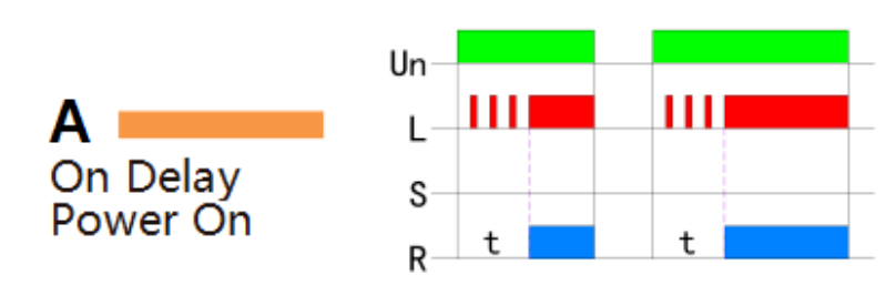
When the input voltage U is applied, timing delay t begins.Relay contacts R change state after time delay is complete.Contacts R return to their shelf state when input voltage U isremoved. Trigger switch is not used inthis function.
Loop Delay 1: Automatic L;oop "Perpetual Alarm Clock"
When the input voltage U is applied, timing delay t begins.When time delay t is complete, relay contacts R change statefor time delay t. This cycle will repeat until input voltage U isremoved.Trigger switch is not used in this function.
Disconnect Delay: Guardian Who Remains "Online" After Power Outage
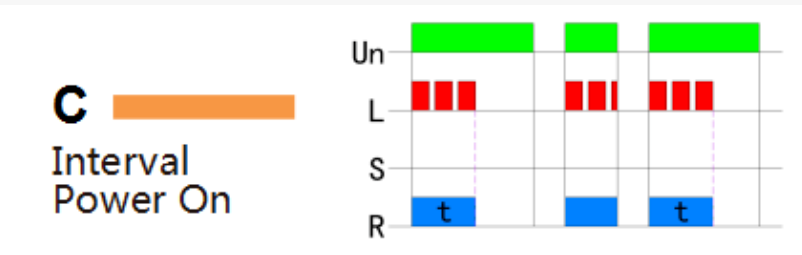
When input voltage U is applied, relay contacts R changestate Immediately and timing cycle begins. When time delayis complete,contacts return to shelf state. When inputvoltage Uis removed, contacts will also return to their state.Trigger switch is not used in this function.
Trigger Mode 1: Signal-Driven “Precise Response”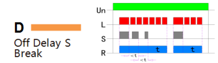
Input voltage U must be applied continuously. When triggerS is closed, relay contacts R change state. When trigger S isopened, delayt begins. When delayt is complete, contacts Rreturn to their shelf state. If trigger S is closed before timedelay t is complete, then time is reset. When trigger S isopened, the delay begins again, and relay contacts remain intheir energized state, if input voltage U is removed, relaycontacts R return to their shelf state.
Trigger Mode 2: "Smart Switch" Triggered By Multiple Conditions.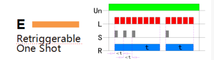
Upon application of input voltage U, the relay is ready to accepttrigger signal S.upon application of the trigger signal S, the relaycontacts R transfer and the preset time t begins.At the end ofthepreset time t, the relay contacts R return to their normal conditionunless the trigger signal S is opened and closed prior to time out t(before preset time elapses).Continuous cycling of the triggersional S at a rate faster than the preset time will cause the relaycontacts R to remain closed.lfinput voltage U is removed, relaycontacts R retum to their shelf state.
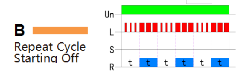
Loop Delay 2: “Work Scheduler” For Staged Loops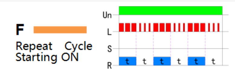
When input voltage U isapplied,relay contacts Rchange state immediately and time delay t beginsWhen time delay t is complete, contacts retumn to theirshelt state for time delay t lhis cycle will repeat untllinput voltage Uis removed. Trigger switch is not usedin this function.
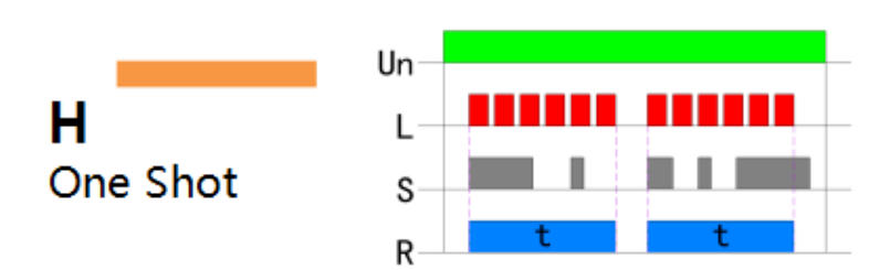
Pulse Mode: "Flash" That Exerts Power Instantly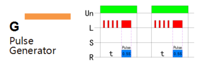
Upon application of input voltage U,a single outputpulse of 0.5 seconds is delivered to relay offer timedelay t. Power must be removed and reapplied torepeat pulse. Triggerswitch S is not used in thisfunction.
Trigger Mode 3: Remote Controlled “Executor”
Upon application of input voltage U ,the relay is readyto accept trigger signal S Upon application of thetrigger signalS,the relay contacts R trasher and thepreset time t begins. During time-out,the trigger signaS is ignored. lhe relay resets by applying the trggersignalS when the relay is not energized.
Trigger Mode 4: Combination Triggered “Decision Master”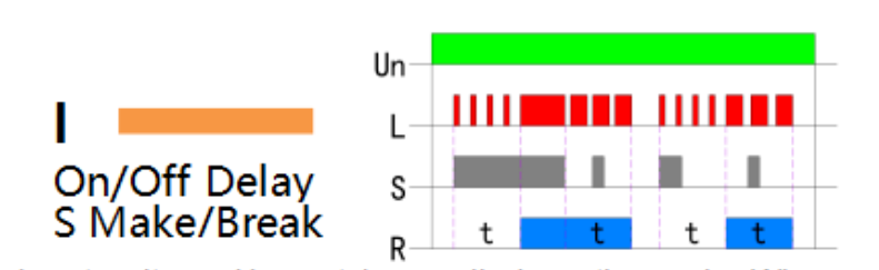
Input voltage U must be applied continuously. Whentrigger S is closed,time delay t begins. when time delayt is complete, relay contacts R change state and remaintransferred until trigger S is opened,lfinput voltage U isremoved, relay contacts R retum to their shelf state.
Step-By-Step Mode: “Process Commander” for orderly advancement.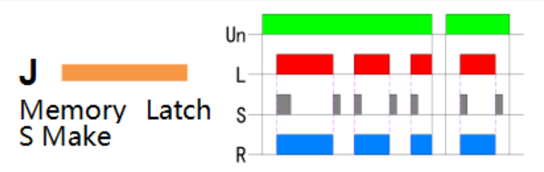
Input voltage U must be applied continuously. Outputchanges state with every trigger S closure. lf inputvoltage U is removed, relay contacts R return to their original state.
Use "Time" As a Pen to Draw N Possibilities of Automatic Control
01
Function Integration: 10 Delay Modes In One
Breaking the single function limitation of traditional relays, it integrates 10 kinds of time logic such as power-on delay and power-off delay. It does not require the combination of multiple devices and can switch modes by selecting a gear. It can adapt to complex scenarios from industrial timing control to smart home linkage. It can be called a "one-stop time solution".
02
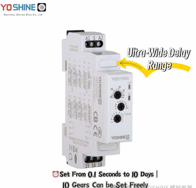
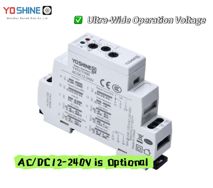
Accurate And Flexible Time Control
Ultra-wide delay range + ultra-wide operating voltage: delay time covers 0.1 seconds to 10 days, and supports AC/DC voltage range selection from 12 to 240V to adapt to different power supply environments.
03
Strong cross-domain adaptability
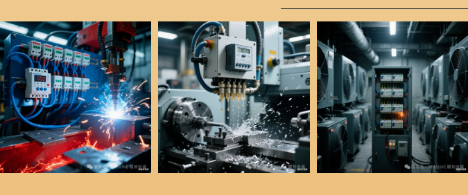
Industrial scenario: solve problems such as batch starting of multiple motors (to prevent power grid impact), machine tool lubrication timing, and pulse heating of welding equipment; Civilian scenarios: Supports light cycle flashing (stage special effects), air conditioning compressor delay protection, and smart curtain multi-condition triggering .
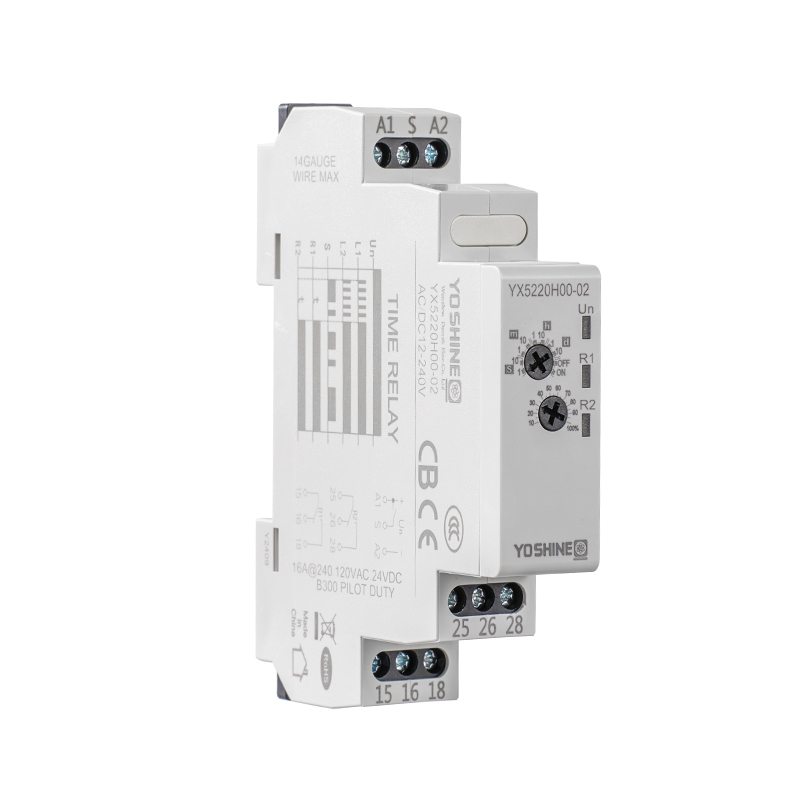
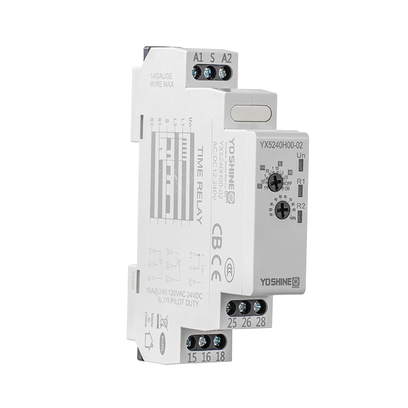
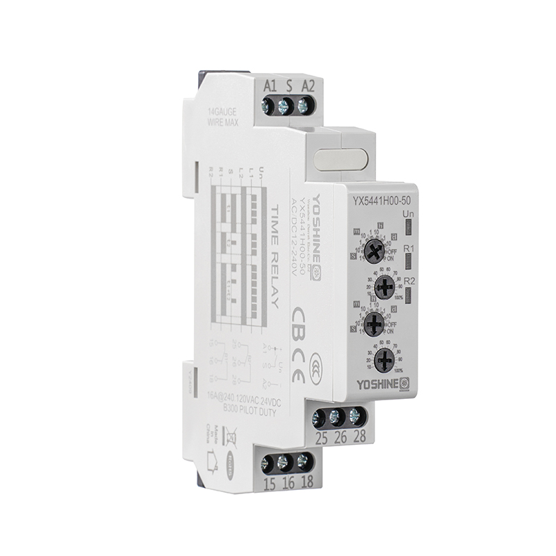
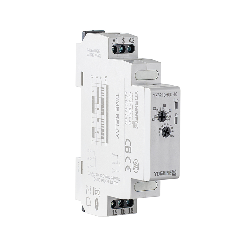
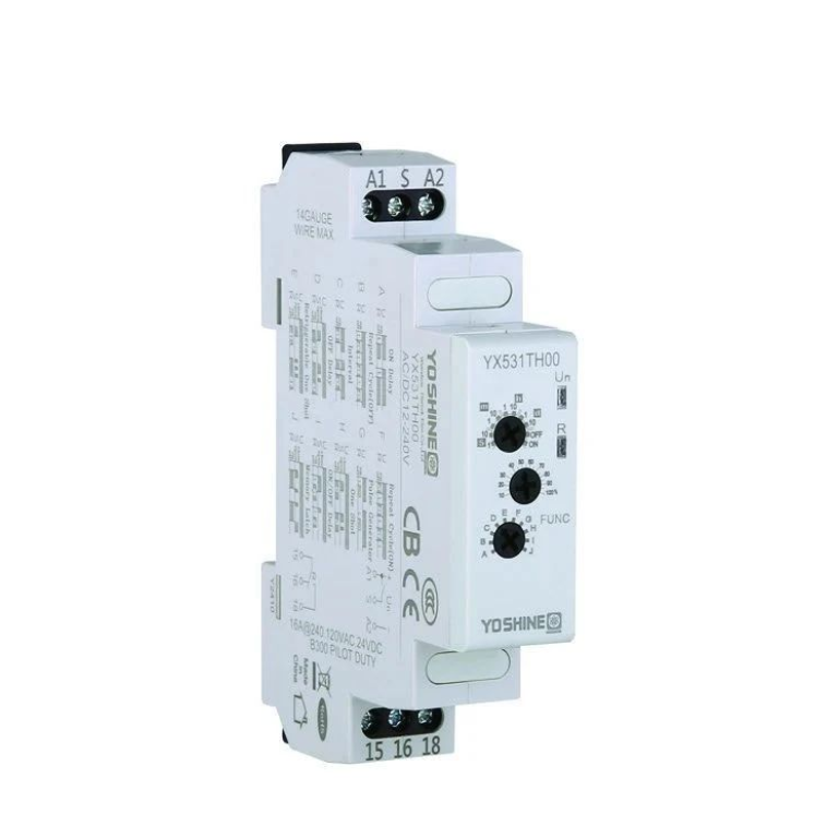
Specifications That Define Industrial Reliability In Numbers
| Product Brand |
YOSHINE |
| Product Name |
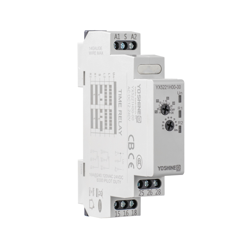
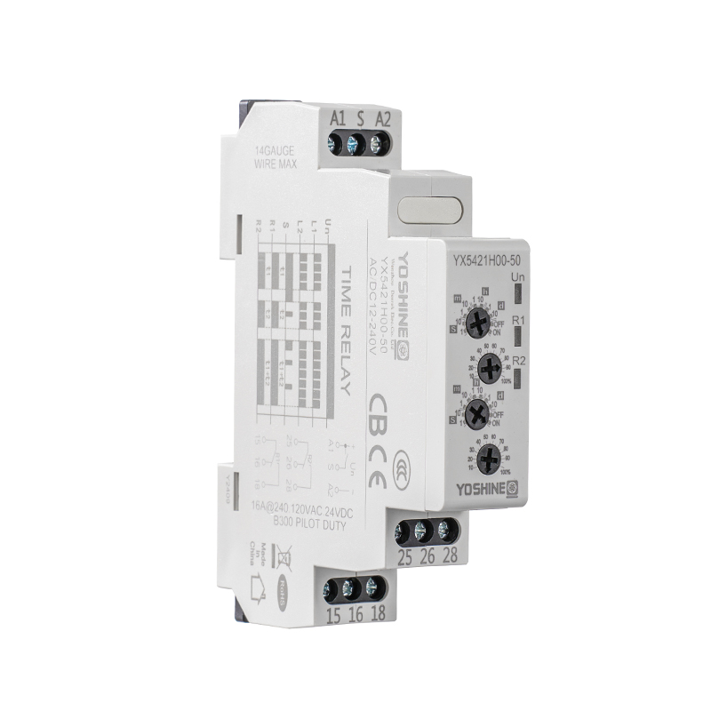
Ten-Function Time Relay |
| Working Voltage |
DC12V,DC24V,AC110V,AC220V,ACIDC12-240V,ACIDC24-240V |
| Input |
SPDTIDPDT10A Or 16A |
| Delay Range |
From 0.1 seconds to 10 days |
| Dielectric strength |
Between Shell and Contacts:2500VAC Between Contacts: 1000VAC |
| Ambient Temperature |
Working:-20 to+55℃ Keeping:-30 to+70℃ |
| Mechanical Life |
1x7^7 |
| Electrical life |
1x10^5 |
| Protection Level |
IP20 |
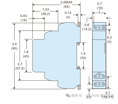
Relays Smaller Than The Palm Of Your Hand: Compress Control Cabinet Space By 50%
Simple Wiring, Turning Wiring Into An "Instinctive Reaction"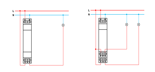
Without Trigger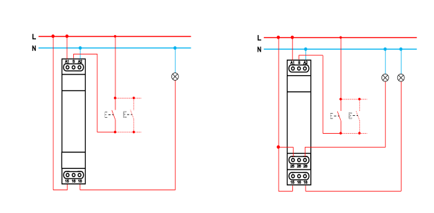
With Trigger

Popular Products
Have Questions?
Get in Touch!
Our aim is to provide the market and the customers with high quality products like Pulse Relays and customized solutions.
Zhiguang Industry Zone, Liushi Town, Yueqing, Wenzhou, Zhejiang, China.
+86-13819765860
 English
 русский
 Español