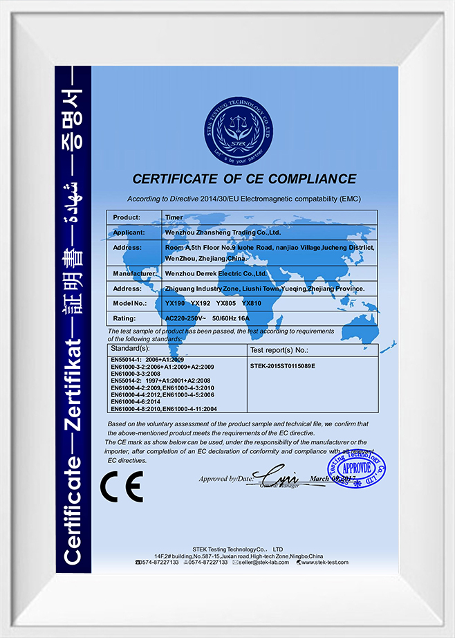
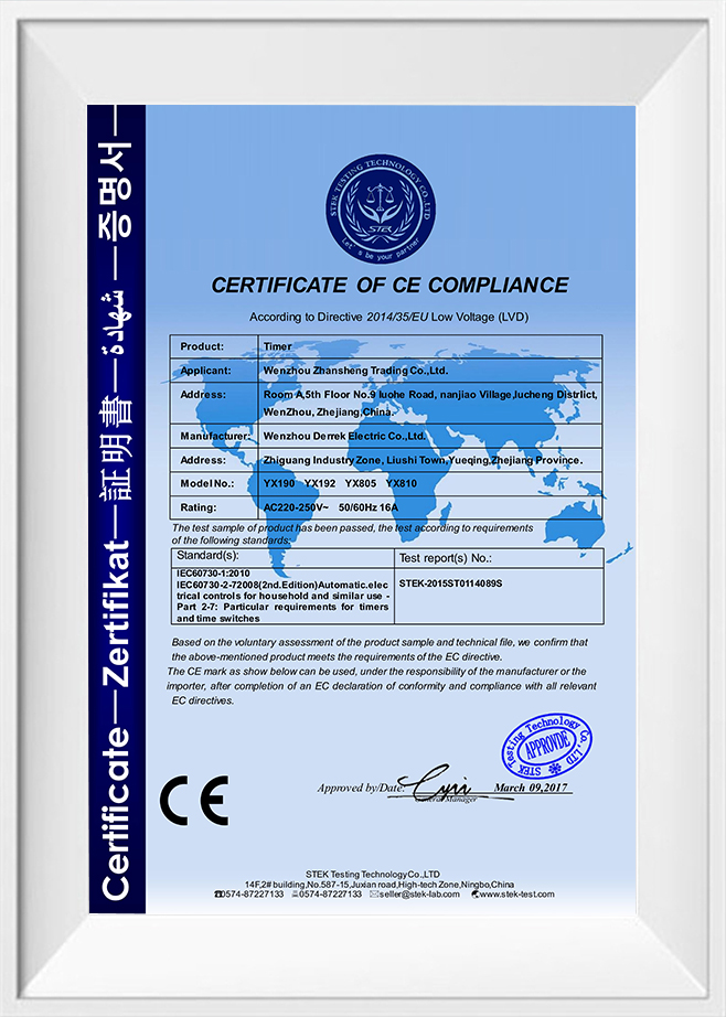
English
 русский
 Español
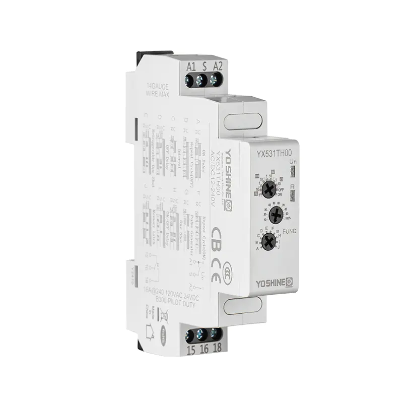
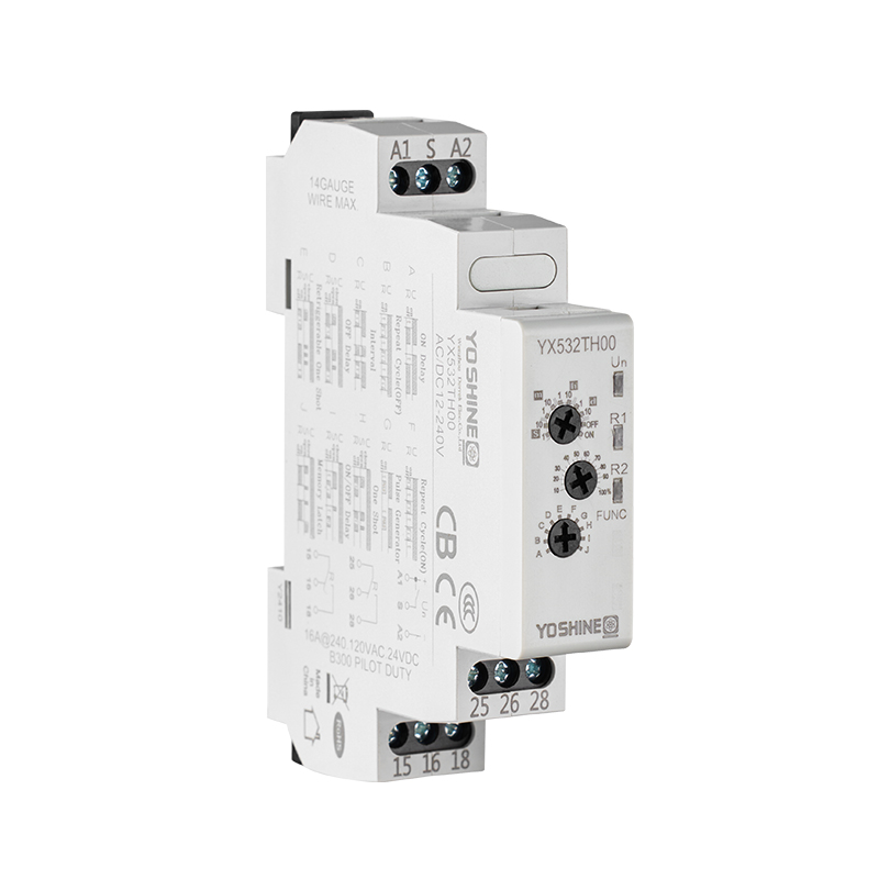
YOSHINE Ten Funtion SDPT Rail Type Multi-Function Time Relay
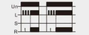
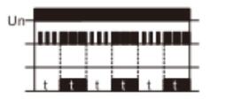
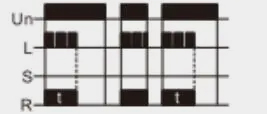
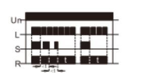
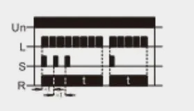
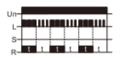
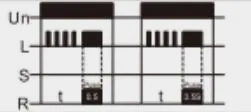
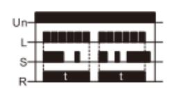
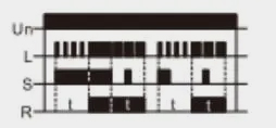
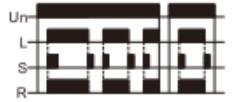
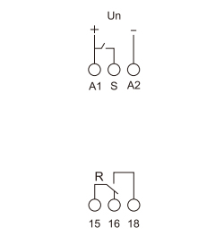
The Ten Function SDPT Rail Type Multi-Function Time Relay is designed to provide versatile timing control in industrial and automation systems. With its dual contact configuration, it allows precise management of electrical circuits, making it suitable for a wide range of applications. This relay supports ten different timing functions, enabling users to select the optimal mode for their specific needs, from delay on/off to pulse or cyclic operations.
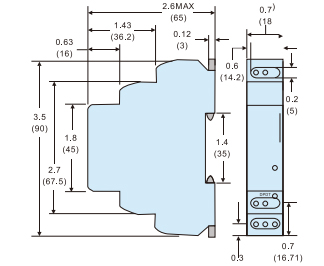
Its rail-mount design ensures easy installation on standard DIN rails, saving space and simplifying maintenance. The device delivers stable performance even under fluctuating voltage conditions, ensuring reliable operation in demanding environments. Compact yet robust, it is suitable for control panels, machinery, and process automation where precise timing is critical. Easy to adjust and highly adaptable, this multi-function time relay enhances efficiency, reduces manual intervention, and supports accurate automation workflows across various industrial sectors.