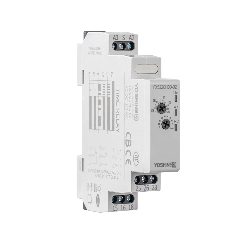
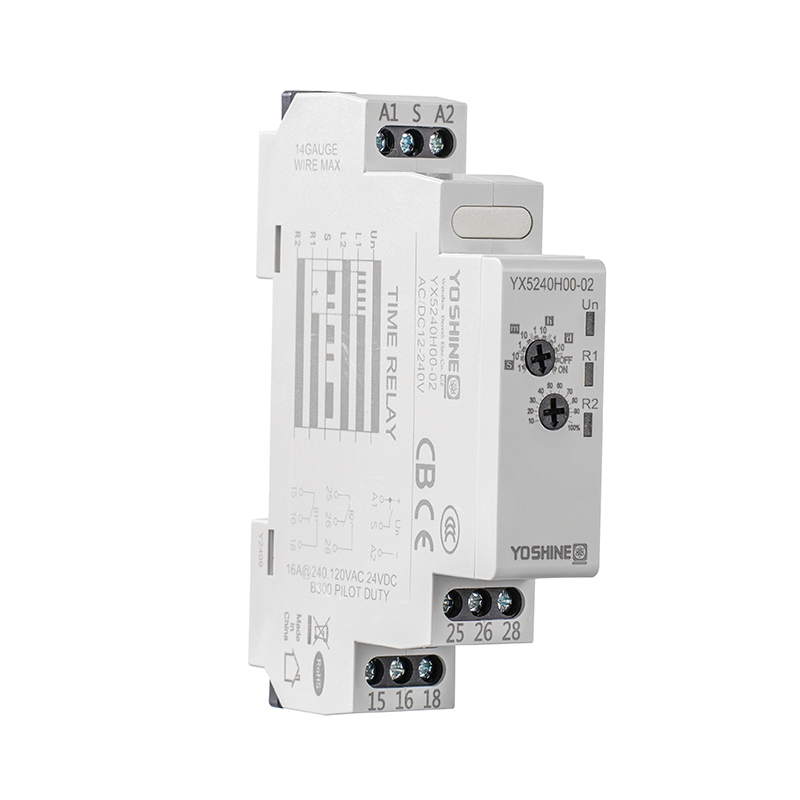
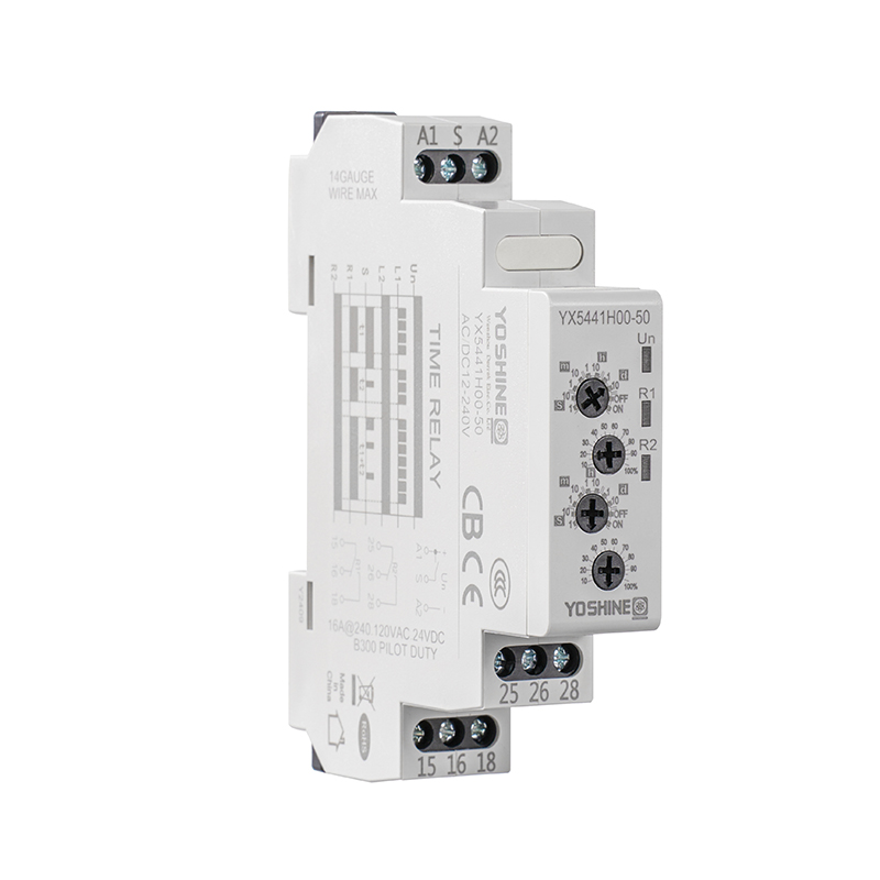
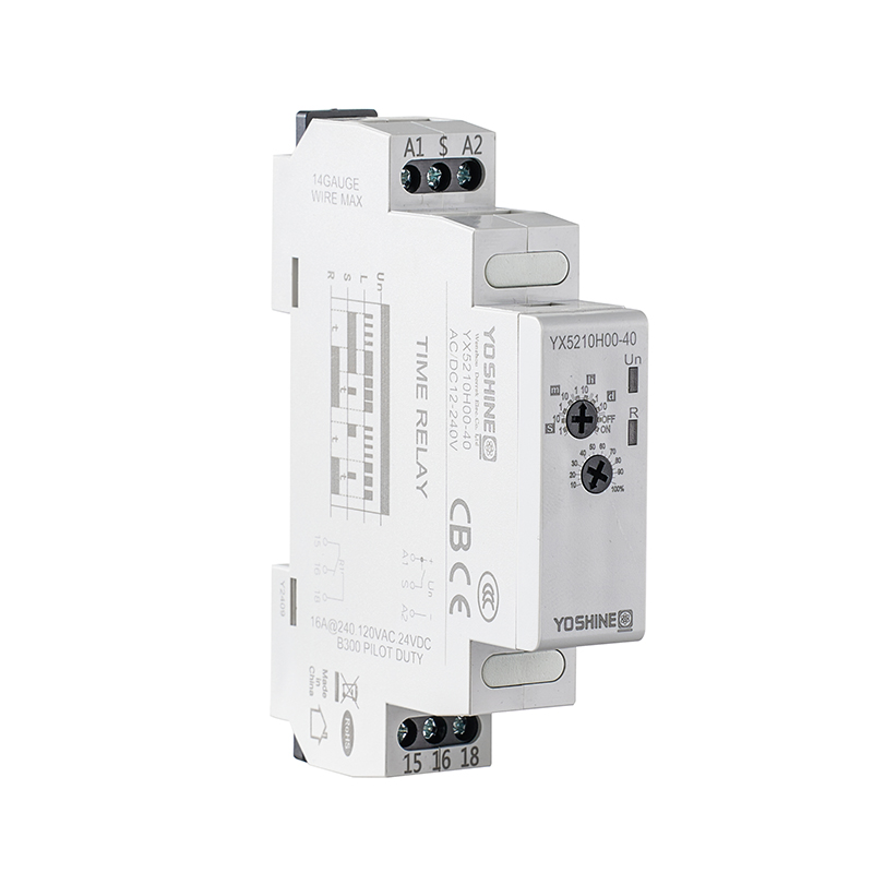
Relays play a genuinely important role in electrical control systems because they allow one part of a circuit controlling another without requiring the operator handling every switching action directly. Although standard relays and pulse relays share this basic purpose, they respond to control signals in genuinely different ways, which affects how they get used in lighting systems, industrial automation, equipment operation, and other electrical applications.
Understanding these differences helps engineers design control circuits that fit their operating needs, while buyers can use the same knowledge comparing products before placing an order.
A standard relay is an electrically operated switch that changes the state of its contacts when its control input gets activated. In a common arrangement, the relay remains energized while the control signal stays present, and its contacts return to their normal state when that signal gets removed, although the exact behavior depends on the relay design.
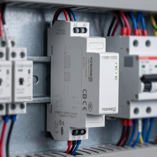
This operating pattern suits circuits where a device needs following a continuous command, such as keeping a motor control circuit active while a run signal remains present. Standard relays can also separate a low-power control signal from the circuit being switched, helping control equipment operate through a dedicated electrical interface.
Their straightforward behavior makes them useful in control cabinets, machine panels, lighting circuits, and equipment that responds directly to an external command.
A pulse relay changes its contact state in response to a brief control signal, rather than requiring the same signal remaining present throughout the entire operating period. In many designs, a short pulse causes the relay changing state, and the new state remains after the triggering signal has ended.
This behavior allows a momentary input controlling a circuit that needs to stay on or off until another command arrives. A Pulse Relay Switch can therefore prove useful when a push button, sensor, or control device needs changing an operating state without holding its output active continuously.
The precise behavior depends on the relay type, so buyers should check whether the selected model changes state with each pulse, responds to a particular input sequence, or follows another control method.
The main difference concerns the relationship between the input signal and the relay's output state. A standard relay commonly follows the presence or absence of its control signal, while a pulse relay can use a brief trigger changing or controlling an output state that persists afterward.
| Comparison Point | Standard Relay | Pulse Relay |
| Input behavior | Often follows a sustained control signal | Can respond to a brief trigger |
| State behavior | Commonly follows the energized condition | May retain its changed state |
| Control method | Suitable for direct on/off commands | Suitable for momentary commands |
| Typical use | Interlocking and equipment control | Lighting and state-changing circuits |
| Circuit design | Often based on continuous control | May reduce the need for sustained input |
These differences don't mean one relay type replaces the other in every application, because each design serves a genuinely different control requirement. The appropriate choice depends on how the system receives commands, how long the output needs remaining active, and whether the circuit must remember its previous state.
A short pulse is a brief electrical command that tells a control device performing an action without requiring the command staying active. This approach proves useful when an operator presses a button switching a light or changing a machine state and then releases the button immediately. The control input doesn't need remaining active merely because the controlled circuit must continue operating.
A Pulse Output Relay can support this type of arrangement by changing its output in response to the specified trigger, provided the input and output functions match the application. The design can also help reduce unnecessary continuous energization in suitable circuits, although the actual energy use depends on the relay construction and the wider control system.
Engineers should confirm how the relay handles repeated pulses, because some designs toggle their state while others perform a defined output action.
State holding means a relay can retain an output condition after the triggering signal has ended. A momentary button, for example, may trigger a relay that keeps a lighting circuit on until another command changes its state. This arrangement differs from a circuit that requires a continuous control signal maintaining the same output condition.
A Pulse Latching Relay uses a latching mechanism or design that retains its contact state without requiring the same continuous energization used by many conventional relay arrangements. Depending on the product, the relay may change state through alternating pulses, separate set and reset inputs, or another specified control method.
The distinction matters during circuit design because the control logic needs matching the relay's actual operating sequence. Engineers should also consider what happens after a power interruption, since state retention and recovery behavior vary by product design.
A Pulse Counter Relay gets intended for applications where incoming pulses need counting or where an output action depends on a defined count. Instead of responding only to a single on/off command, this type of device uses incoming pulse events as part of its control logic.
A production process, for example, may use sensor signals tracking repeated movements, completed cycles, or items passing a detection point. When the configured counting condition gets reached, the relay may change its output or trigger another action according to its design.
This function differs from the simple state-changing behavior associated with many pulse relays, even though both can use short input signals. Buyers should check whether a product performs counting internally or whether it only provides a relay output that must get controlled by an external counter. The distinction can affect the wiring arrangement, the control equipment required, and the way the system gets tested before operation.
Industrial automation often combines sensors, controllers, switches, and actuators coordinating equipment movements and operating sequences. Within this arrangement, a pulse relay can provide a way converting a momentary command into a defined switching action.
A sensor may generate a brief signal when a component reaches a certain position, while the relay changes an output state that controls another part of the process. A Pulse Output Relay may also serve as an interface between a control signal and a separate circuit when its electrical ratings and switching function suit the task.
This proves useful in applications where the control command stays brief but the resulting action needs continuing. The relay must still match the control logic, because an incorrect response to repeated signals may cause an unexpected state change. Production teams should consider the sequence of commands, the expected output behavior, and the effect of a power interruption before choosing a relay for automated equipment.
A programmable logic controller, commonly called a PLC, manages machine operations by receiving input signals, processing programmed instructions, and controlling outputs. Relays can form part of the interface between a PLC and external electrical circuits when the application requires a suitable switching arrangement.
A pulse relay may prove useful when a PLC output provides a brief command that needs changing a circuit state. The PLC program must account for the relay's input requirements and its response to repeated signals, rather than treating every relay as an identical on/off device. Some systems may also use a standard relay when the output needs following a continuous command, instead of retaining a state after the signal ends.
Engineers should review the PLC output type, the relay's control input, the connected load, and the intended switching sequence before integrating the components. The wiring diagram should make clear which device generates the pulse, which component retains or changes the state, and which circuit receives the output.
Lighting control is a familiar application for pulse-operated switching because users often want a brief button press changing a light's state. A suitable pulse relay can allow a momentary wall button switching a lighting circuit without requiring the button remaining pressed.
This arrangement can prove useful in corridors, shared spaces, offices, and other locations where several control points may be part of the same lighting system. The installation must get designed around the relay's contact arrangement, supply requirements, and the electrical characteristics of the connected lights.
A standard relay may still be appropriate when lighting needs following a sustained command from a timer, controller, or other device. The decision depends on whether the circuit needs direct signal-following behavior or a state change triggered by a short command.
Equipment start and stop circuits can use different relay arrangements, depending on how the machine gets expected to respond to commands. A standard relay may suit a control circuit that remains active while a run signal stays present, provided the wider circuit includes the required safeguards.
A pulse relay may suit a design where a brief input changes an operating state and the state remains until another command or reset condition occurs. The difference becomes important when operators use momentary push buttons, rather than maintained switches.
The circuit designer needs considering the machine's required response after power loss, emergency stopping, fault detection, and restart requests. A pulse relay shouldn't get treated as a substitute for safety-rated control equipment when the application requires dedicated safety functions. The relay's role should get clearly defined within the wider control circuit, including how the system handles conflicting commands and unexpected input signals.
Energy use depends on how the relay gets built and how it operates within the complete circuit. Some latching designs consume energy mainly during a state change, while other relay types may require continued energization maintaining an operating condition.
This difference can make a pulse or latching relay useful in applications where the output state needs remaining unchanged between commands. However, a pulse relay doesn't automatically use less energy in every installation because the control circuit, connected load, and switching frequency also influence overall consumption.
Buyers should distinguish between the energy consumed by the relay coil and the energy used by the equipment controlled through its contacts. A relay that switches a lighting circuit, for example, doesn't remove the power required by the lights themselves. Product documentation can help buyers assessing the relay's operating method and understanding whether its design fits the intended energy-management objective.
A relay must be suitable for the electrical load it controls, not just for the signal that triggers it. Different loads can place genuinely different demands on the relay contacts, particularly during switching or when equipment starts operating.
Engineers should review the type of load, the circuit's operating conditions, and the contact arrangement required by the application. The control input also needs matching the available signal, including its electrical characteristics and expected pulse behavior.
A Pulse Relay Switch selected without checking these details may not respond as intended or may be unsuitable for the connected circuit. Buyers should review the manufacturer's documentation, rather than assuming products with similar names share the same operating characteristics.
DIN rail mounting gets commonly used organizing electrical control components inside a cabinet or panel. A relay designed for this mounting arrangement can get installed alongside other compatible control devices, helping keep the cabinet layout orderly and accessible for maintenance.
The space available around each component still matters because wiring, identification, inspection, and replacement all require practical access. Pulse relays and standard relays may have genuinely different physical designs, so buyers should confirm mounting compatibility before planning a cabinet layout.
The control cabinet design should also account for the wiring paths between the PLC, relay inputs, relay outputs, and connected equipment. Clear circuit identification can help maintenance staff understand which relay controls a particular function and how the output state gets expected to change.
B2B buyers often need evaluating genuinely more than the basic relay function when sourcing products for production, distribution, or equipment assembly. The selection process may include operating method, control input compatibility, contact arrangement, mounting style, documentation, packaging, and supply consistency.
A Pulse Counter Relay should get evaluated according to its counting function, while a Pulse Latching Relay should get assessed according to how it changes and retains its state. Product descriptions should distinguish these functions clearly, so purchasing teams don't confuse a counting device with a simple pulse-triggered switch.
| Sourcing Factor | What Buyers Can Review |
| Operating method | Whether the relay follows, latches, or counts pulses |
| Control input | Compatibility with the available trigger signal |
| Contact arrangement | Suitability for the connected load |
| Mounting style | Compatibility with the existing cabinet layout |
| Documentation | Wiring diagrams, ratings, and compliance records |
| Packaging and supply | Consistency across repeat or bulk orders |
For OEM projects, buyers may also need discussing terminal layout, housing requirements, labeling, packaging, and other application-specific needs with the supplier. Export orders can require relevant conformity documents or certification records, depending on the destination market and product category. Buyers should verify the applicable requirements for their intended market, instead of assuming one certificate covers every country or installation.
A useful comparison begins with the control behavior required by the application, rather than the product name alone. The buyer should identify whether the output must follow a sustained signal, change after a brief pulse, retain its state, or respond to a count.
The intended use also helps clarify whether the relay needs connecting with a PLC, working with momentary buttons, fitting a DIN rail, or operating within a particular control cabinet. Suppliers can then get asked providing wiring diagrams, operating instructions, contact information, and relevant compliance documents for the selected model.
A clear specification also helps avoiding substitutions that look similar but respond differently to the same input signal. When evaluating options, purchasing teams should compare the actual switching behavior and installation requirements alongside supply conditions and documentation, so the selected relay fits the circuit it's intended controlling.

Popular Products
Have Questions?
Get in Touch!
Our aim is to provide the market and the customers with high quality products like Pulse Relays and customized solutions.
Zhiguang Industry Zone, Liushi Town, Yueqing, Wenzhou, Zhejiang, China.
+86-13819765860


 English
 русский
 Español