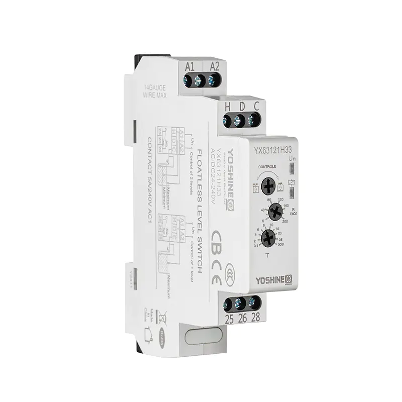
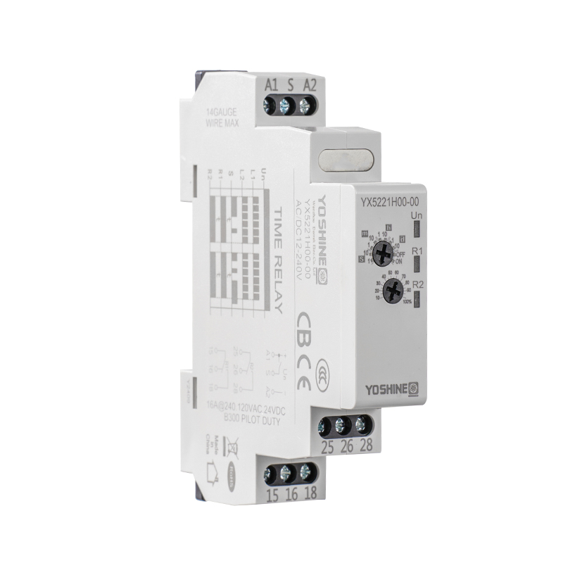
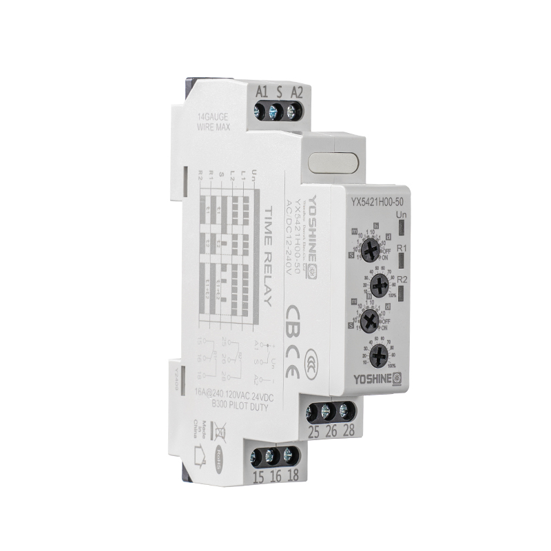
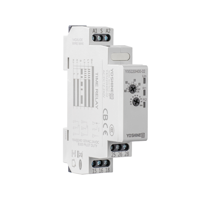
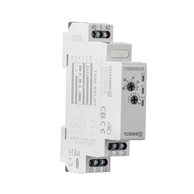
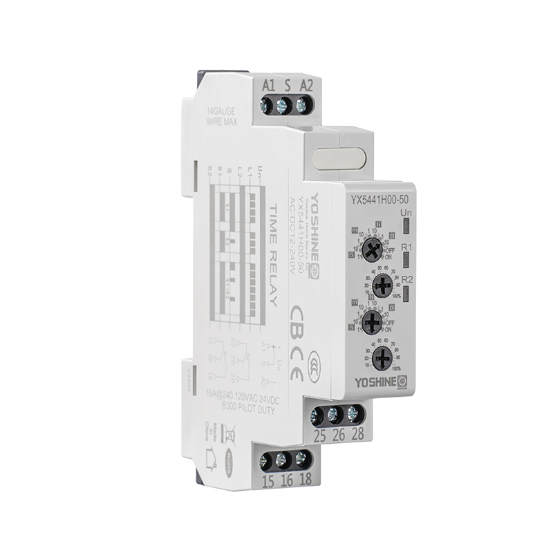
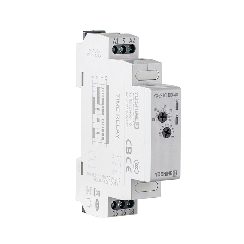
Production lines are more connected now, sensing is smarter and machine control reacts faster. In that setting, reliable pulse detection matters more than it used to. A Pulse Counter Relay, a Pulse Output Relay and a Pulse Relay Switch all handle signals in industrial control systems. How well they do it depends on how the electrical signals are generated, carried, detected and processed. When a count comes out wrong, the relay isn't always the culprit. Sensor characteristics, pulse timing, electrical interference, input response and equipment compatibility can each shift the final number.
A Pulse Counter Relay is a control device that takes in pulses, recognizes valid signal transitions and registers them using its internal counting logic. Some designs can also trigger an output once a preset count is reached.
On a production line, a proximity sensor, photoelectric sensor, encoder or similar device sends a signal each time an object passes a detection point or a machine finishes a movement. The relay has to recognize every valid pulse. It must not mistake electrical disturbances for extra events.
The signal usually moves through these stages:
A Pulse Output Relay can pass a switching or pulse signal on to another control device. A Pulse Relay Switch can handle controlled switching between connected circuits. Their outputs have to suit the equipment that receives them.
This matters because a correct count at the input doesn't guarantee correct behavior at the output. Engineers should follow the whole signal path. Treating each device as a separate part leaves gaps.
The electrical nature of an incoming signal decides whether a pulse counter can recognize an event. A sensor may seem to work fine and still deliver an output that doesn't meet the relay's input needs.
A pulse counter relay registers a signal when its electrical level crosses the required input threshold.
If the sensor's output voltage stays below that threshold, the relay may miss a valid pulse. Voltage swings also make detection patchy, especially over long cable runs or on shared power supplies.
Engineers should check:
A mismatch between sensor output and relay input can cause intermittent counting errors, even though each device is within its own specification.
Pulse width is how long a signal stays active. If the pulse is shorter than the relay's allowed detection time, the input circuit may not see it.
Shape counts as well. A distorted waveform, a slow transition or an unstable edge makes it hard for the relay to separate a real event from noise.
| Signal characteristic | Possible problem | Engineering consideration |
|---|---|---|
| Low signal voltage | Missed pulses | Verify input threshold |
| Short pulse width | Incomplete detection | Check minimum pulse duration |
| Slow signal transition | Unstable recognition | Inspect sensor output characteristics |
| Voltage fluctuation | Inconsistent counting | Check power supply stability |
| Contact bounce | Repeated triggering | Review debounce settings |
Look at the real waveform. Don't lean only on the sensor's nominal output description.
Industrial sensors come with different output types, including NPN, PNP and relay contact outputs.
These don't always connect directly to every pulse counter relay. Switching behavior, current needs and common reference connections must match the receiving input circuit. A PNP sensor wired to an input built for a different switching arrangement, for instance, may never be recognized reliably.
Before installation, read the sensor wiring diagram and the relay input specifications side by side.
Production equipment runs at changing speeds, so the pulse frequency from sensors changes too. This is a real concern on automated conveyors, rotary machinery, packaging equipment and motion control.
A relay that counts well at low speed may start dropping counts when the machine speeds up.
Pulse frequency is how often valid pulses reach the relay input.
Every pulse counter has a limit on how fast it can process input. Go past the permitted range and the relay may fail to pick out individual pulses. That can lead to:
Choose the maximum input frequency from the sensor's actual output under working conditions. Take acceleration and speed changes into account too. Checking only steady running isn't enough.
Response time is how fast the input circuit recognizes and reacts to a signal transition. It shouldn't be judged apart from pulse width and the gap between pulses.
A signal can sit at an acceptable frequency and still go unregistered if its active time is shorter than the relay needs.
| Parameter | Engineering significance |
|---|---|
| Maximum input frequency | Sets the permitted pulse arrival rate |
| Minimum pulse width | Defines the shortest detectable active signal |
| Minimum pulse interval | Sets the required separation between events |
| Input response time | Affects how quickly a transition is recognized |
| Filtering time | Determines how short disturbances and pulses are treated |
A good habit is to compare the full sensor waveform with the relay's input specifications. A device rated for a certain frequency won't necessarily catch every waveform at that frequency.
Modern plants mix variable-speed motor control, connected sensors, switching power supplies and distributed control gear. That makes the electrical environment harder on low-voltage control signals.
A pulse signal may share a cabinet or cable route with circuits that produce disturbances. Without good installation practice, those disturbances can upset signal recognition.
Variable frequency drives set motor speed by fast electronic switching. That switching can produce conducted and radiated interference.
When sensor cables run close to motor cables or drive output wiring, stray signals can couple into the pulse input. They show up as extra transitions or a distorted waveform.
Picture a conveyor sensor that detects products correctly, yet the counter logs extra pulses whenever a nearby motor changes load. That is a classic case.
Engineers should consider:
Poor grounding can create unwanted voltage differences between devices. Those differences can shift the reference level the relay uses to recognize incoming signals.
Weak shielding also leaves low-level sensor signals open to electromagnetic disturbance.
When counting is unstable, inspect the grounding of the sensor, relay, power supply and control cabinet. Terminate shields as the equipment maker requires. An arbitrary grounding scheme can add interference instead of removing it.
Input filtering and debounce functions help suppress unwanted transitions. Too much filtering, though, can block short pulses that are perfectly valid.
So there's a trade-off:
Set filtering from the real pulse waveform and the relay's documented input characteristics.
A pulse counting circuit is more than a relay. The sensor, power supply, signal wiring, receiving controller and output device all shape the result.
A component can meet its own electrical specs and still perform badly when connected to something incompatible.
Before choosing a Pulse Counter Relay, compare the sensor's electrical output with the relay's input requirements. Key points:
This catches interface problems before they turn into repeat production faults.
A Pulse Output Relay may send a switching signal to a programmable controller, a counter or another receiving device. That input must be able to recognize the signal under the intended operating conditions.
A Pulse Relay Switch may also control an external circuit. Its contact or electronic output must suit the connected load.
| Equipment parameter | What engineers should verify |
|---|---|
| Output voltage | Compatibility with the receiving input |
| Output current | Within contact or electronic output ratings |
| Switching frequency | Suitable for the intended switching activity |
| Contact arrangement | Correct connection and switching logic |
| Electrical isolation | Proper separation between connected circuits |
| Operating temperature | Within installation conditions |
Mechanical relay contacts and solid-state outputs behave differently when they switch. Consider contact bounce, leakage current and switching response when choosing an output type. Base the choice on the real control task, not on the product name.
An unstable supply voltage can disturb the internal operation of electronic counting circuits. Temperature, vibration, humidity and cabinet conditions can affect performance as well.
Where conditions change, verify the relay's operating temperature range, mounting requirements, enclosure protection and power supply specifications. A compatible electrical interface is necessary. The installation must also stay within the manufacturer's stated limits.
When a pulse counter relay gives inconsistent readings, swapping it out straight away may not fix the root problem. A structured check can separate sensor faults, transmission problems, interference and configuration issues.
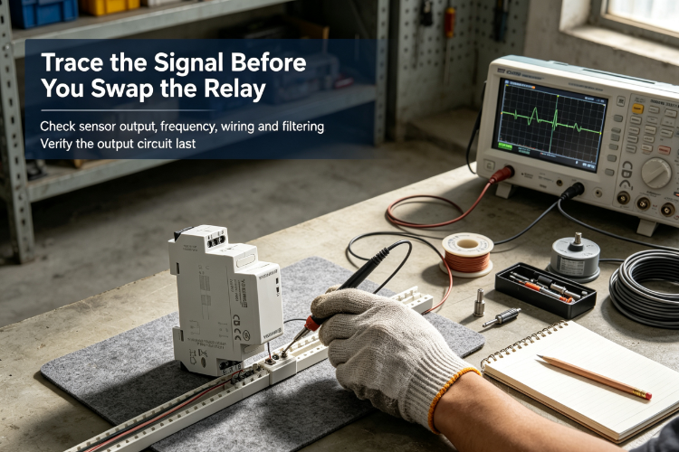
Take an automated packaging line where the counter sometimes registers fewer products than the sensor detects. The inspection can run in this order.
Step 1: Inspect the sensor output.
Use an oscilloscope or other suitable instrument to examine the output waveform during real machine operation. Check that voltage level, pulse width and switching transitions meet the relay's input requirements.
Step 2: Compare the pulse frequency with the relay specifications.
Watch the system while machine speed changes. Confirm the sensor's output frequency stays inside the relay's permitted input range.
Step 3: Examine the wiring arrangement.
Look at terminal connections, cable damage, shielding and grounding. Pay special attention to signal cables routed near motors, contactors and variable frequency drives.
Step 4: Review input filtering and configuration.
Check whether filtering or debounce settings are suppressing valid pulses. Confirm the input mode matches the sensor's output arrangement.
Step 5: Verify the complete output circuit.
See whether the Pulse Output Relay or Pulse Relay Switch gives a signal the receiving controller can use. Inspect output connections, switching behavior and load requirements.
This approach avoids needless part swaps and gives a clearer picture of the real fault.
A suitable Pulse Counter Relay should fit the sensor's electrical characteristics and the machine's operating needs. Choosing by counting function alone can hide important interface limits.
Engineers and purchasing teams should review these specifications before deciding.
| Selection criterion | Questions to consider |
|---|---|
| Input signal type | Does the relay support the connected sensor output? |
| Input voltage | Is the signal voltage within the permitted range? |
| Maximum frequency | Can the relay keep up with the machine's speed? |
| Pulse width | Can it detect the sensor's actual output duration? |
| Response capability | Does its input behavior suit the application? |
| Filtering options | Can noise be cut without suppressing valid signals? |
| Output configuration | Is the output compatible with the receiving equipment? |
| Environmental rating | Does the device suit the installation environment? |
In high-speed counting, pay particular attention to pulse width and input response. In electrically noisy installations, also review signal isolation, grounding, cable routing and documented interference resistance. In retrofits, compatibility with existing sensors, controllers and cabinet wiring can shape the whole installation.
At RelayFactory, pulse relay requirements are evaluated around the actual control application. That helps engineering and purchasing teams find suitable product configurations. Don't pick a device from its general description. Give the sensor specifications, signal type, operating frequency and output requirements when you discuss a Pulse Counter Relay application.
Unstable pulse counting can disrupt production monitoring, throw off machine coordination and create extra troubleshooting work.
The right configuration starts with understanding the electrical signal and the conditions the system runs in.
Whether you need a Pulse Output Relay, a Pulse Relay Switch or a Pulse Counter Relay, you can contact RelayFactory to discuss the input characteristics, output configuration and installation conditions you require.
Contact RelayFactory to talk through your industrial pulse relay requirements and find a configuration that suits your control system.

Popular Products
Have Questions?
Get in Touch!
Our aim is to provide the market and the customers with high quality products like Pulse Relays and customized solutions.
Zhiguang Industry Zone, Liushi Town, Yueqing, Wenzhou, Zhejiang, China.
+86-13819765860


 English
 русский
 Español