Press a hallway button once and the lamp turns on. Release the button and the lamp stays on. Press again and it turns off. That everyday behavior depends on a relay that keeps its contact position after a short command ends. Many electrical systems need this kind of memory of the current state, not only a switch that follows a held signal.
Engineers and buyers meet several product names in this area. A Pulse Output Relay, a Pulse Relay Switch, and a Pulse Counter Relay can all appear in control panels, yet each name describes a different idea. What matters is how the device receives signals, changes its contact position, and reacts to later commands.
State-based control manages equipment according to its present condition: on, off, open, closed, or another defined position. A command is read in light of what the device is already doing.
Lighting is the familiar case. A brief press changes the lamp, and the lamp holds that condition after the button returns. Compare this with a standard relay, which needs a continuous signal to stay energized. Remove the signal and the contact drops back. A latching design can keep its contact position without that continuous input, depending on its construction.
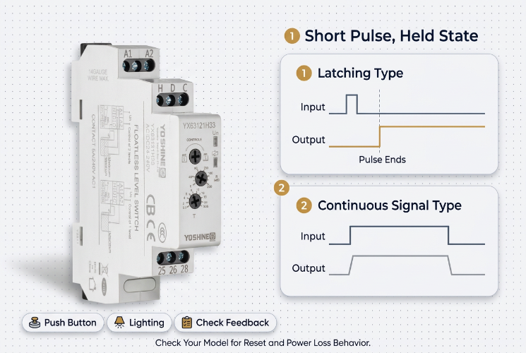
This makes operation easier. Nobody has to hold a switch, and one control panel can manage several functions through short presses.
Holding a contact position is not the same as full system memory. After a power interruption, the contact may remain where it was, but the wider control system may not know it. Auxiliary contacts or feedback circuits are needed when the state must be confirmed.
The relay responds to a short electrical command that moves its contacts, then stays in position after the command ends. Internal design decides how. Some use a magnetic structure to hold the position, and others use different arrangements. Control methods differ as well: some use separate set and reset inputs, while others change state with each successive pulse.
A simple sequence looks like this:
The length of the command and the length of the output state become independent. An operator does not keep a finger on the button.
A Pulse Output Relay may appear in sequences where a short output signal is one step. Check whether a given product provides a held contact state, a momentary output, or another response, because similar names cover different functions. Wiring diagrams and product documents should guide installation, since input count, contact layout, reset behavior, and response to power loss vary by model.
Lighting often uses momentary push buttons. A corridor with buttons at each end is a good example. Each button sends a brief command to a relay, and the relay switches the lighting circuit. Several control points can then operate one load without complicated wiring between switches.
A Pulse Relay Switch suits arrangements built on momentary buttons or other pulse sources. Its fit depends on contact design, control input, load needs, and wiring method.
Designers should decide how the system reacts when commands arrive close together, such as a local button pressed while a central controller sends a signal. Behavior must be predictable.
Indication deserves thought too. A button that sends a pulse does not show whether the lamp is on. If users need confirmation, add an indicator or a feedback connection from the output side. In shared spaces and commercial buildings, clear state display saves confusion for both occupants and maintenance staff.
A panel gathers switches, indicators, relays, and protection devices into one interface. A latching relay separates the command from the held output. A button or external controller sends a short signal, the relay changes state, and the connected circuit follows.
Typical uses include enabling a circuit, selecting an operating mode, or keeping a device in a chosen condition after the initiating signal ends.
The designer must define what each input does. One input may set the device active and another may reset it, while a different design may toggle on every pulse. These methods are not interchangeable.
A clear sequence answers these questions:
A closed contact also does not prove the load is working. A motor or lamp may have its own fault or supply problem, so separate sensing may be needed to confirm actual equipment condition.
A pulse is a brief command, and logic decides what the system does with it. State holding connects the two by keeping the result active.
In toggle arrangements, each pulse flips the output between two conditions. Set and reset arrangements use direct commands instead, which suits systems that should not depend on the previous state.
Multiple sources complicate matters. A local button, a remote controller, and an automated routine may all address one relay. Without coordination, the resulting state may surprise the operator. Define priority, for instance letting an emergency shutdown override normal switching. The relay itself may not decide this, so the surrounding circuit must.
A Pulse Counter Relay may count pulse events or use a count to influence an output. That differs from a latching relay that flips with each pulse, so review its counting method and output response before selecting it.
| Arrangement | General Idea | Point to Verify |
|---|---|---|
| Pulse latching relay | A pulse changes and holds a contact state | State retention and reset behavior |
| Pulse output device | A short output signal is generated | Duration and signal type |
| Pulse counter relay | Pulse events are counted and drive an output | Counting method and output response |
| Continuous-control relay | A held signal keeps the coil energized | Response when the signal is removed |
Categories can overlap across product ranges, so circuit diagrams and technical documents should settle how a particular device is used.
Start from the control task: what must change, how the command is produced, and how long the result must last.
A relay that works on a test bench may act differently when connected to several control sources and a complex load, so review the full circuit before installation.
Wiring should follow the manufacturer's diagram. Mixing up a set input, a reset input, and a load terminal can cause unexpected switching or damage connected equipment.
Test the intended sequence. Check how the relay responds to each command, whether the output holds, and whether repeated operations give the expected result. Where local and remote controls coexist, test every control point within the complete arrangement.
Check indicators as well. One wired to the relay output reflects the actual condition, while one wired only to the control signal shows that a command was sent, not that the load changed.
During maintenance, inspect connections, wiring condition, and signs of heat or mechanical damage. Inconsistent switching may come from the relay, the signal, the load, or a loose terminal, so replacing the relay alone may not fix it.
Good documentation helps. A panel diagram should show the relay's role, input commands, output connections, and feedback path, with labels that tell a technician whether a pulse turns a device on, off, or toggles it. For equipment makers and system integrators, this discipline gives a more predictable arrangement: the relay performs the switching, and the surrounding logic decides when and how the held state is used.

Popular Products
Have Questions?
Get in Touch!
Our aim is to provide the market and the customers with high quality products like Pulse Relays and customized solutions.
Zhiguang Industry Zone, Liushi Town, Yueqing, Wenzhou, Zhejiang, China.
+86-13819765860


 English
 русский
 Español