A refrigeration compressor in a small shop clicks off every afternoon when the neighbouring workshop starts its machines. The owner suspects the compressor. The real cause is a voltage dip on a shared supply, and a relay with poorly chosen limits either trips on every dip or ignores a harmful one. A Single Phase Voltage Relay watches the supply and reacts when voltage leaves a configured range. Setting that range takes more than picking two numbers. The load's tolerance, the normal behaviour of the supply, and the installation all matter.
The overvoltage threshold is the upper boundary. When measured voltage rises past it, the relay changes its output state and can trigger a contactor or other disconnecting device, depending on the model. The undervoltage threshold is the lower boundary, used to catch supply that has dropped too far for the connected equipment.
Together they form a protection window. Voltage inside the window is treated as acceptable, and voltage outside it can trigger a response. The window does not replace the equipment maker's permitted range or the rules that apply to the installation.
| Setting | Purpose | Main Consideration |
| Overvoltage threshold | Flags voltage above the permitted setting | Upper operating limit of the load |
| Undervoltage threshold | Flags voltage below the permitted setting | Lower operating limit of the load |
| Response delay | Sets how long a condition must persist | Length of normal supply fluctuations |
| Recovery setting | Defines when normal supply is recognized again | Stable return to acceptable voltage |
Not every relay offers every adjustment. Read the product instructions to see which settings exist and how the output behaves when a limit is crossed.
A pump, a control board, and a refrigeration unit tolerate different voltage ranges. The nameplate or manual gives the range each was designed for. When several devices share a circuit, the settings must respect all of them and not just the one you worry about most.
A threshold outside the load's permitted range lets a harmful condition continue. A threshold sitting too close to everyday variation causes repeated trips that the equipment could have ridden out. Both outcomes weaken the protection.
If documents are missing or devices have conflicting needs, confirm the limits with the equipment supplier or a qualified electrician.
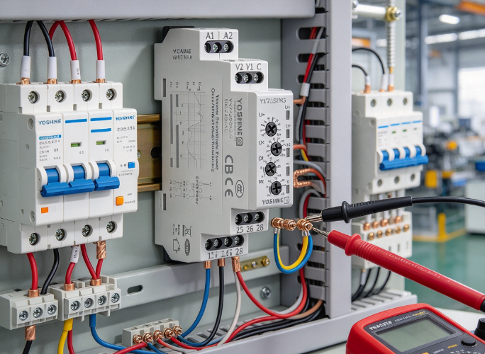
Supply voltage moves. It dips when a motor starts nearby and rises when a large load switches off. The size and length of these swings depend on the building, the wiring, and the utility connection.
A relay that reacts to every small change interrupts production, resets electronic controls, or switches off household appliances for no good reason. A relay that ignores persistent changes leaves the load exposed. Measure the supply with suitable instruments across a normal working cycle, including startups, shutdowns, and load changes.
| Observed Condition | What to Consider |
| Brief rise | Is it a short, normal event? |
| Brief drop | Does it coincide with a motor starting? |
| Repeated fluctuation | Do the supply or loads need investigation? |
| Sustained deviation | Is protective action required? |
| Instability after a load change | Does the circuit arrangement need review? |
The aim is not to make the relay overlook normal behaviour. It is to separate acceptable variation from conditions that threaten the load.
Set the upper limit with the load's tolerance in mind. A limit placed too high lets voltage linger above the intended range, and one placed too low trips on ordinary supply changes.
A sensible sequence:
If the supply often drifts near the load's upper limit, investigate why. Widening the relay window only hides the cause.
Low voltage makes motors struggle to start or run and can make electronic equipment reset or behave unpredictably. Tie the lower limit to the boundary specified for the load, and allow for dips caused by equipment with a high starting demand on the same supply.
A limit set too high trips during routine load changes. A limit set too low allows an unsuitable condition to continue. Neither should be chosen only to cut down the number of interruptions.
When dips repeat, look for loose terminals, an overloaded circuit, undersized wiring, or a weak supply. The relay can detect undervoltage, but it cannot repair the source.
Some models let you set how long an abnormal condition must persist before the relay acts. A short dip while a compressor starts differs from a sustained drop during steady running. A delay can prevent needless disconnection where the equipment tolerates brief variation.
Too long a delay postpones protection when the condition is harmful. Loads that need prompt protection call for a different approach from loads that ride through short changes. Do not assume every relay has an adjustable delay or that one delay suits every application.
Recovery decides when the system treats the supply as healthy again. Depending on the design, the relay may reconnect automatically, wait for a manual reset, or work with an external control arrangement.
This matters because voltage can hover around a limit. Without suitable recovery behaviour, the relay may switch states repeatedly, which interrupts the load and wears connected switching devices. Allow return to service when voltage is acceptable, but avoid restarting during an unstable period.
Review automatic reconnection carefully for loads that could be unsafe or damaged by an unexpected restart, such as workshop machinery or compressors with pressure still in the system.
A relay monitors voltage and changes its output. The actual disconnection may depend on a contactor or another device, and the relay should not be assumed to switch every load directly. Check output ratings against the load before wiring.
Placement changes what the relay sees. Monitoring the incoming supply catches problems affecting the whole circuit, while monitoring one branch protects specific equipment. Correct wiring and suitable overcurrent protection remain necessary alongside voltage monitoring.
Where wiring, switching capacity, or coordination with other protective devices is uncertain, ask a qualified professional to review the design.
Adjusting a threshold without understanding the existing situation can make protection less suitable. If the relay trips during normal operation, the limits may not match the supply, or a real voltage problem may exist. A review might include:
After configuration, confirm that the relay responds when voltage leaves the window and that the connected control arrangement operates correctly. Follow the manufacturer's instructions and site safety procedures. Do not create a dangerous overvoltage or undervoltage on live equipment just to watch the relay trip. Qualified personnel should use suitable test equipment and a controlled method.
Check the output, any delay, and recovery behaviour. Also confirm that the relay does not interfere when supply stays in range.
Warning signs include repeated nuisance trips, slow protective action, and equipment faults that coincide with voltage changes. These symptoms do not prove the configuration is wrong, since wiring, a connected switching device, or the measurement arrangement may be responsible. Compare observed behaviour with the documented operation, and ask whether new loads, altered wiring, or supply changes have occurred since the settings were chosen.
Record settings and test results. Adjust by documented review and not by repeated trial and error.
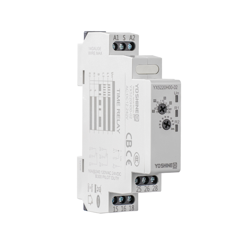
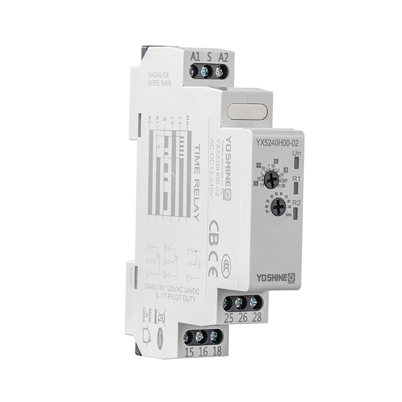
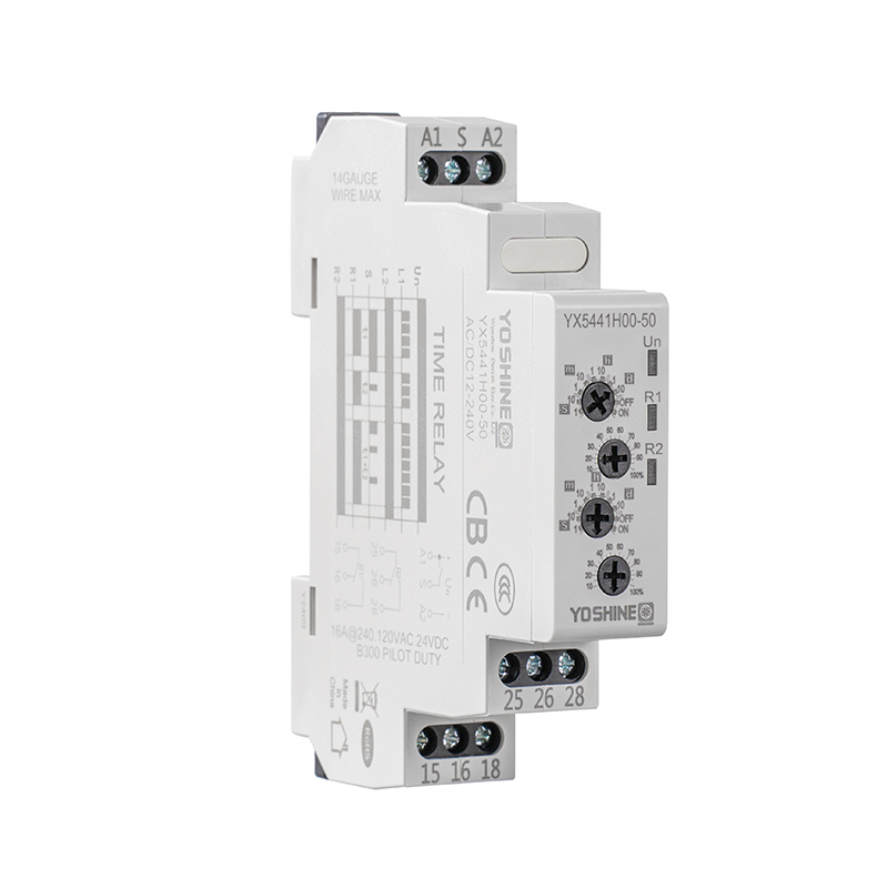
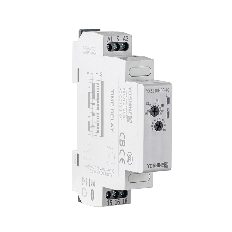
Buyers should match the relay to the equipment and installation. Look at the available threshold range, how adjustment is made, response behaviour, recovery options, and output arrangement. Clear documentation helps users understand available settings.
Practical details count too. Mounting space, access for adjustment, visible status indicators, and ease of inspection affect daily use. Where many units serve one facility, consistent product identification and recorded settings make maintenance simpler.
A Single Phase Voltage Relay works well when it is selected and configured around the load's permitted range and the real behaviour of the supply. Limits chosen that way make protection predictable and keep unnecessary interruptions down.

Popular Products
Have Questions?
Get in Touch!
Our aim is to provide the market and the customers with high quality products like Pulse Relays and customized solutions.
Zhiguang Industry Zone, Liushi Town, Yueqing, Wenzhou, Zhejiang, China.
+86-13819765860


 English
 русский
 Español